B-U585I-IOT02A
LED Blinky: How to flash LED on B-U585I-IOT02A board
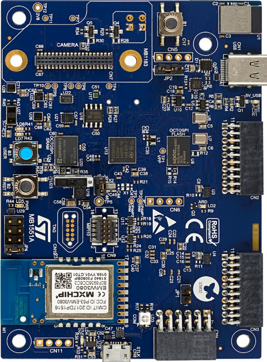
B-U585I-IOT02A is an IoT Discovery Kit from
STMicroelectronics which is based in Ultra-low-power STM32U585AII6Q
microcontroller, along with other peripherals such as 512-Mbit Quad-SPI flash memory,
64-Mbit Octo-SPI PSRAM, 256 Kbit I2C EEPROM, Wi-Fi module from MXCHIP, BLE
module from STMicroelectronics, MEMS sensors from STMicroelectronics (2 digital
microphones, relative humidity and temperature sensor, 3-axis magnetometer, 3D
accelerometer and 3D gyroscope, pressure sensor, 260-1260 hPa
absolute digital output barometer, time-of-flight and gesture-detection
sensor), ambient-light sensor, authentication and security peripherals and IoT
devices, 2 user LEDs, push-buttons, and on-board debugger.
There are not many resources available online for this kit. Let’s see how to make our first demo working – LED Blinky.
· Open STM32Cube IDE.
· Choose your workspace in the prompt.
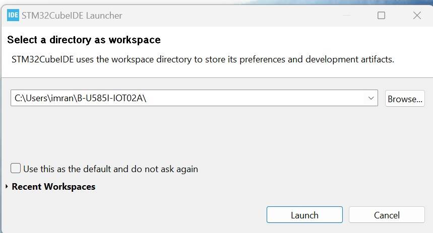
· Press Launch.
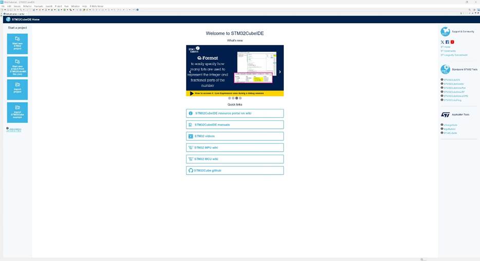
· You will see the IDE Home screen. Select “Start new STM32 project” on the left corner.
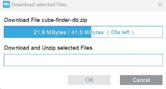
· Let downloading finish for STM32.
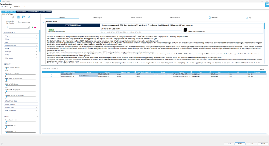
· In the STM32 Project Target Selection window, select MCU/MPU Selector menu item.
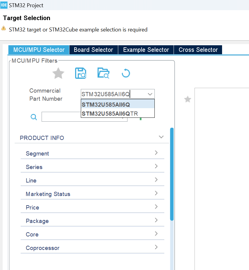
· Write “STM32U585AII6Q” in the “Commercial Part Number” field.
· Select “STM32U585AII6Q” in the “MCU/MPU List” on the right pane on the bottom side, and press “Next”.
· In the STM32 Project window, write “LED_Blinky” as project name, or name it as you wish.
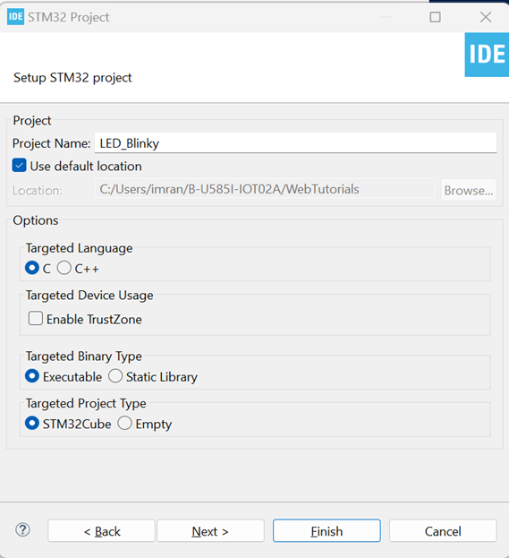
· Press “Finish”.
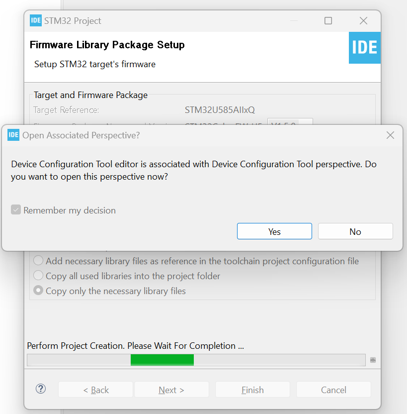
· The prompt for Device Configuration Tool editor shall open. Press “Yes” to open the Device Configuration Tool editor.
· It will start loading IOC.

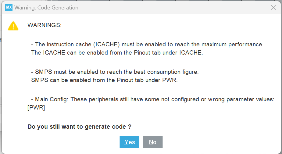
· Press “Yes” when it shows warnings.
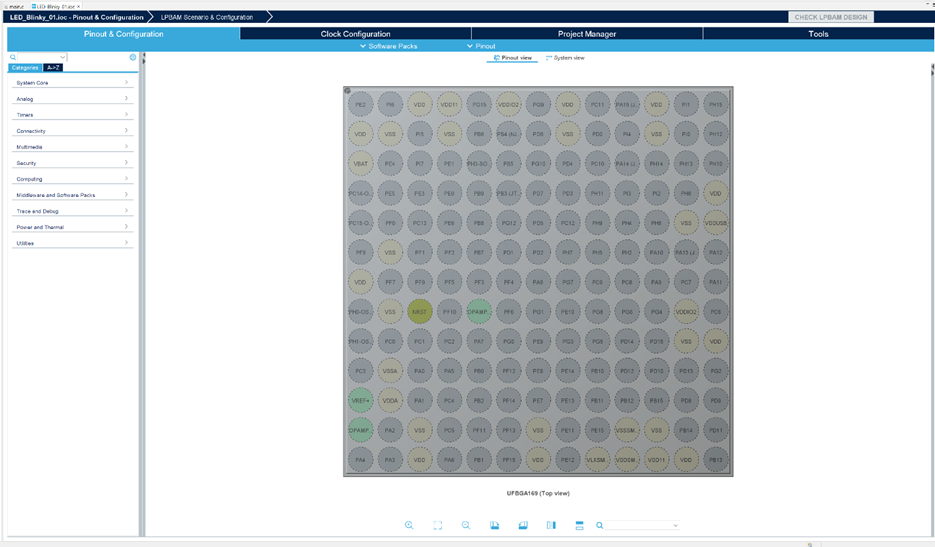
· The IDE Device Configuration Tool shall open .Configuration view.
Now we have to find out which MCU pins are
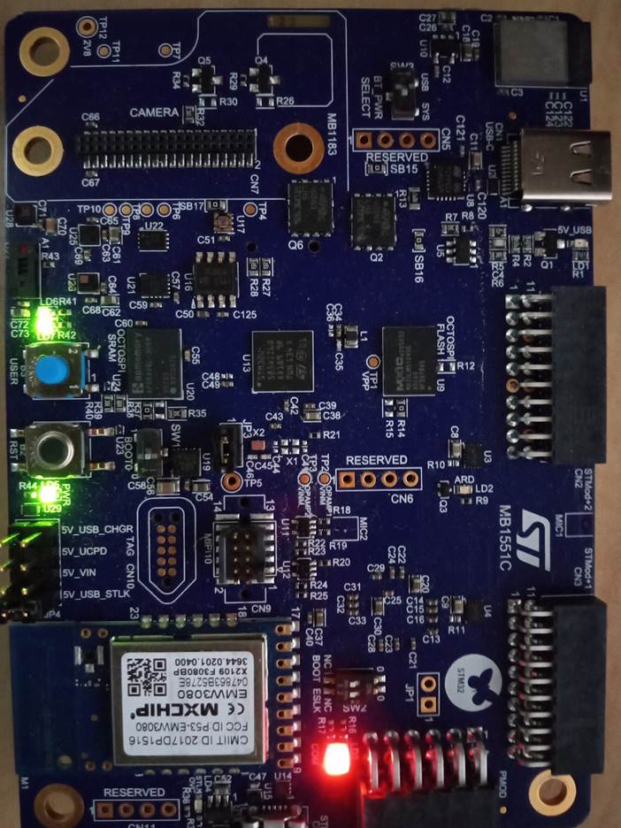
connected to LEDs. We will flash Green LED. So let’s
find out from the schematic.
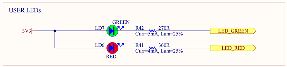
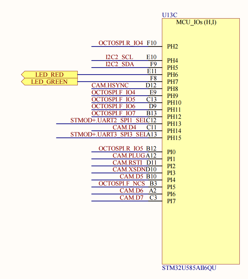
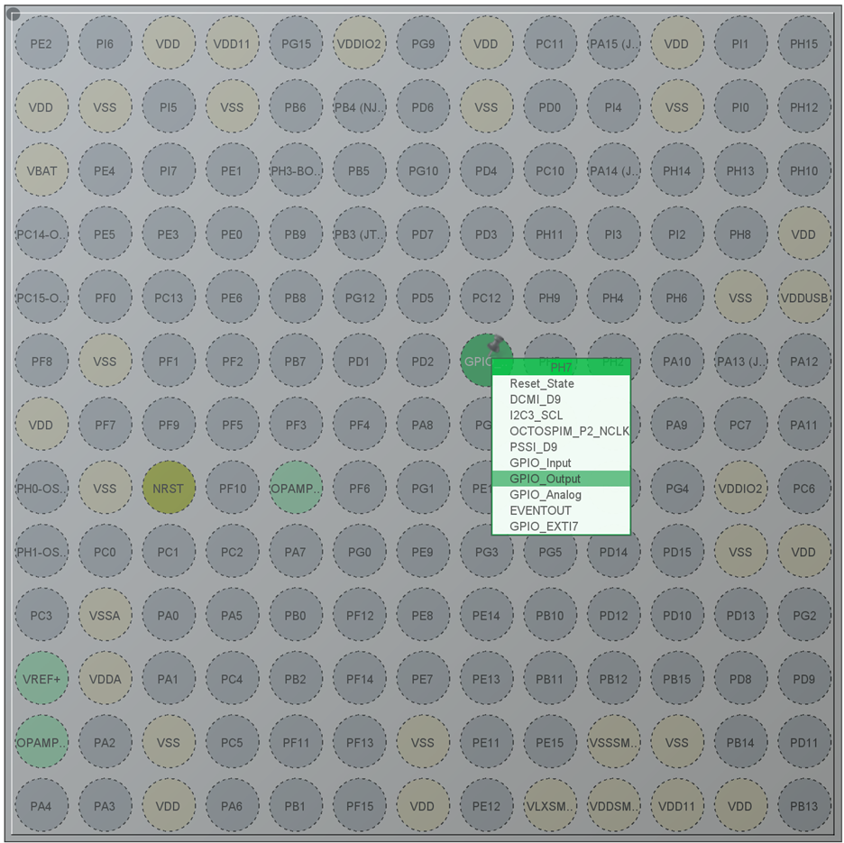
· We can see that Green LED is connected with PH7 pin of the MCU.
· Click on PH7 pin in the Configuration Tool. It will show a drop-down menu where you can select the mode in which you want to configure that pin. Select “GPIO_Output”.
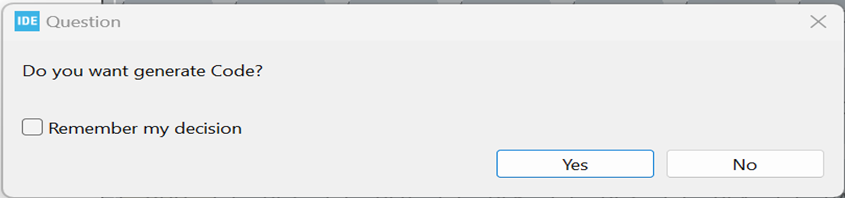
· Press Save icon in the toolbar of the IDE. The IDE shall show the prompt to generate code for the current configuration. Click “Yes”.
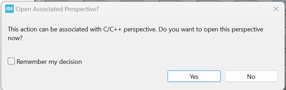
· The IDE shall show prompt for changing perspective. Click “Yes”.
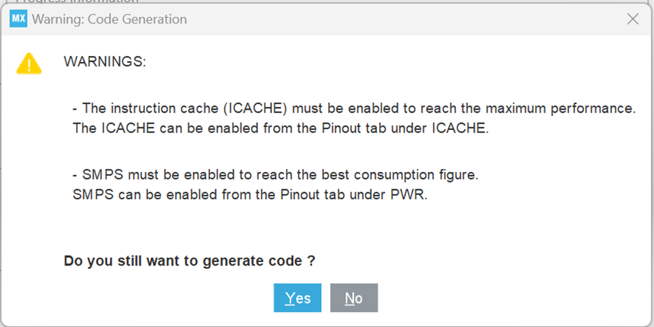
· There will be a Warning. Click “Yes”.
· You will see the static void MX_GPIO_Init(void) function has the Green LED pin initialization.
Now go to while(1) loop in the main function and write this code to turn on/off Green.
/* USER CODE BEGIN WHILE */
while (1)
{
HAL_GPIO_WritePin(GPIOH, GPIO_PIN_7, GPIO_PIN_RESET);
HAL_Delay(1000);
HAL_GPIO_WritePin(GPIOH, GPIO_PIN_7, GPIO_PIN_SET);
HAL_Delay(1000);
/* USER CODE END WHILE */
/* USER CODE BEGIN 3 */
}
/* USER CODE END 3 */
· Alternatively you can also write like this:
/* USER CODE BEGIN WHILE */
while (1)
{
HAL_GPIO_TogglePin(GPIOH, GPIO_PIN_7, GPIO_PIN_RESET);
HAL_Delay(1000);
/* USER CODE END WHILE */
/* USER CODE BEGIN 3 */
}
/* USER CODE END 3 */
· Now compile code. It should compile without giving any error.
· Connect the B-U585I-IOT02A board’s USB debugging port with PC USB. The PC shall open it as a flash drive but you can ignore it and close that window.
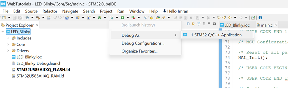
· From the Debug menu toolbar, select “Debug As” “STM32 C/C++ Application”.
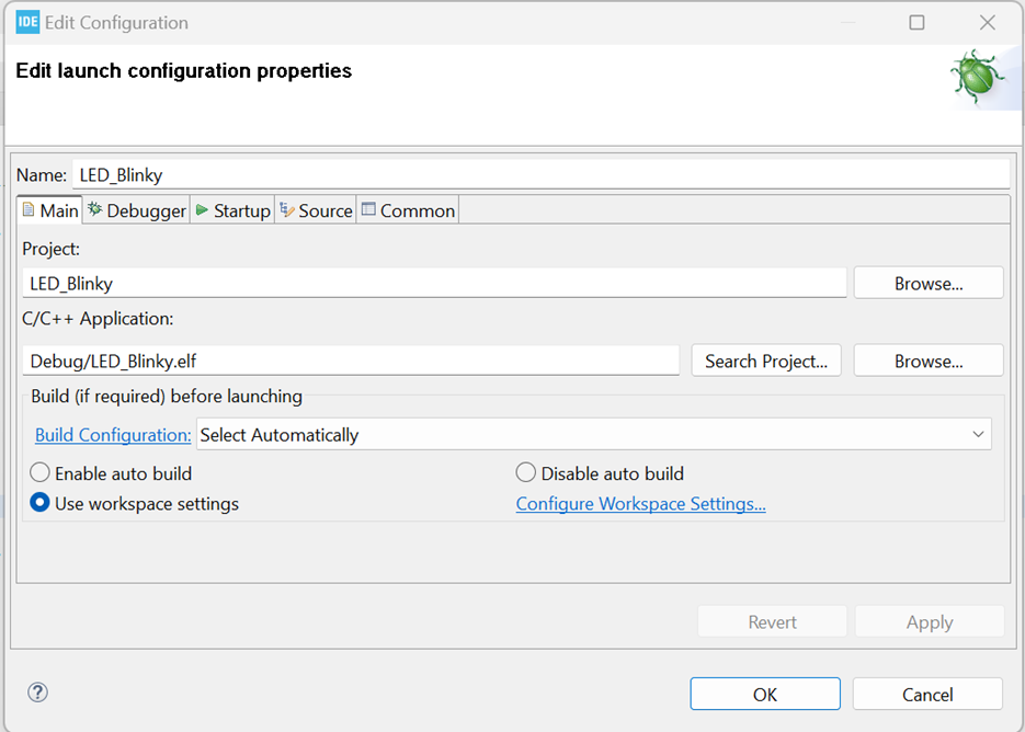
· In the “Edit Configuration” Window. Press “OK”.
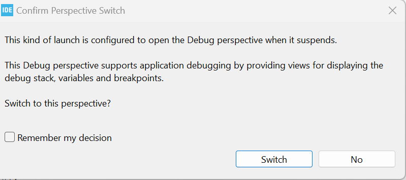
· In the Switch Perspective prompt, select “Switch”. It will start downloading the binary to the MCU on board.
· You should see “Download verified successfully” in the IDE terminal window.
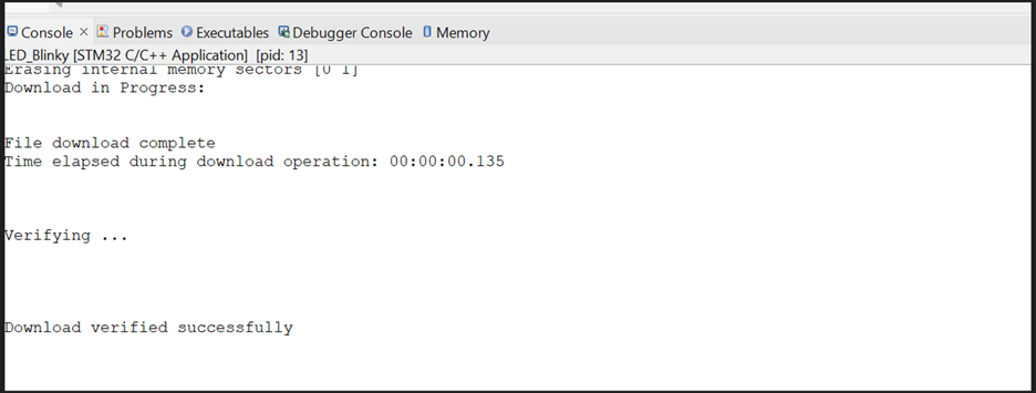
· You should see this kind of window after downloading finishes in the MCU. Press “Run” icon from the toolbar.
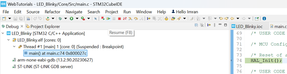
· The Green LED on board should start flashing with approximately 1 second time interval.
· You can download Zipped Code here:
References
STMicroelectronics.
(2021). B-U585AI-IOT02A (DB4410 - Rev 3 - December 2021).
STMicroelectronics.
STMicroelectronics.
(2021). en.MB1551-U585I-C02_Schematic.PDF (B-U585AI-IOT02A).
STMicroelectronics.